FANG 2: CAD part 1
Posted on 2009-02-20 22:59:32
Filed under fang2I started modeling the turret parts in Pro/Engineer today. My intention was to do this earlier, but due to a combination of math problems in reducing the volume of plastic used and laziness I hadn't got around to it yet.
Designing the turret to use less plastic is an interesting exercise in geometry. Right now I'm using a simple configuration that is very low in volume. To lower the volume further would require solving some equations without closed form solutions, which can be a pain to do and then verify if the equations actually are correct, so I might not even go that far.
These designs aren't final but should be reasonable representations of what I plan to do for the first prototype.
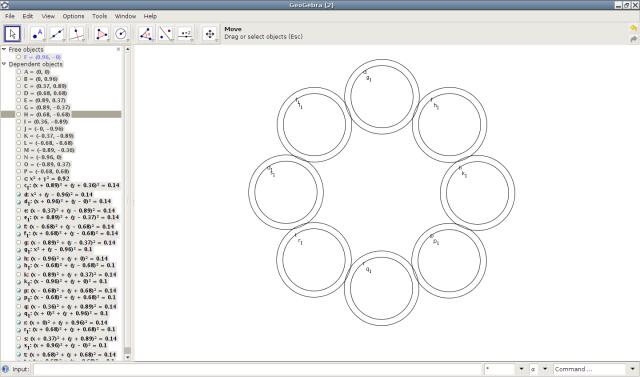
The screenshot above shows my testing out a configuration in the geometry program GeoGebra. I'd recommend that program if you want to screw around with geometry. It's not the best for what I intended to do but it's pretty fun.
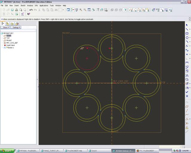
Later I started modeling the turret pieces. The screenshot above shows the front stabilization piece of the turret in sketch mode.
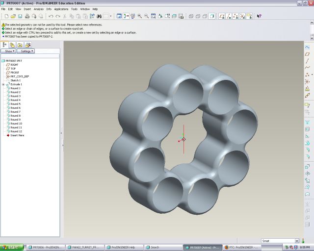
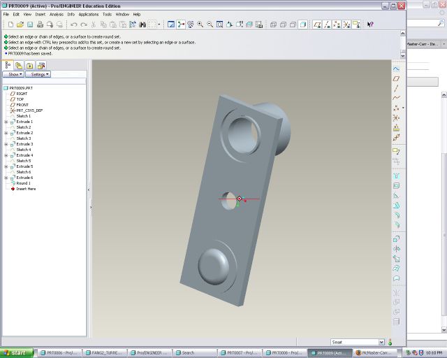
This screenshot shows the rendered front piece.
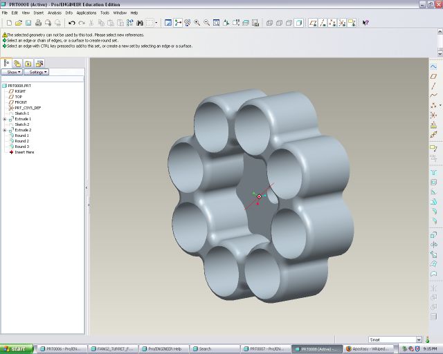
The screenshot above shows the back piece which is essentially the same as the front one aside from the back for the seal and attachment. I neglected to add a fillet between the back piece and the barrel slot--this will be added later.
This screenshot shows the rough plan for the plastic piece to attach the valve to the turret. Note that it is upside down from the intended direction. I do not know if FDM (fused deposition modeling, the rapid prototyping technique I intend to use) can make this piece as shown because FDM drips plastic (and to drip plastic so it floats in mid-air is not possible). I could easily imagine a few workarounds to allow for that in the machine. If FDM can't make this piece I could easily adapt it so that FDM could.
I'm hoping to get these pieces made in the next few weeks so a finished product should be available relatively soon.
I'm also considering a few different loading schemes. The final piece shown is loaded through the side. I think loading through the top might be most convenient so I might have two of the indexes (shown on the top) so I can use the top for the loading slot. I might make different pieces and test them out to see which configuration I like best.
The remaining parts will be modeled soon. I'm still learning CAD but I know probably all I'll need to use to model the remainder.
©2007 - 2010 Ben Trettel
Last modified on 2009-02-20 22:59:32.